Did you know? Without transformers, the modern power system would be impossible. High-voltage electricity from power plants is stepped down through a series of transformers before being safely delivered to your home's electrical outlet. These silent "power guardians" work every day, but few people truly understand their internal components and their respective functions.
This article will take you inside the transformer, disassembling 14 core components and analyzing the structural differences between single-phase and three-phase transformers. After reading, you'll not only be able to name each component but also understand how they work together to perform tasks such as voltage transformation, insulation protection, and heat dissipation.
Basic Working Principle of a Transformer
A transformer is a static device that transmits alternating current using the principle of electromagnetic induction. It does not change the frequency of the electrical energy, only the voltage and current. A typical transformer consists of a closed iron core and two (or more) windings wound around it: the primary winding is connected to the power source, and the secondary winding is connected to the load. When alternating current is applied to the primary winding, an alternating magnetic flux is generated in the iron core. The secondary winding then generates an induced electromotive force due to electromagnetic induction, thus achieving voltage transformation.
For safe, efficient, and long-term operation, transformers require many auxiliary components. These are described below.
I. Iron Core
Definition: The iron core is the magnetic circuit part of the transformer, typically made of stacked high-permeability cold-rolled silicon steel sheets. An insulating layer is coated between the silicon steel sheets to reduce eddy current losses.
Function: It provides a closed magnetic circuit with low magnetic reluctance, allowing the magnetic flux to efficiently couple between the primary and secondary windings; it also confines the magnetic field inside the iron core, reducing leakage flux and electromagnetic interference to surrounding equipment.
Improved Note: The original text's use of "soft iron" is inaccurate; industrial transformers commonly use silicon steel sheets.
II. Windings
Definition: The windings are the electrical circuit part of the transformer, divided into the primary winding (connected to the power supply) and the secondary winding (connected to the load). They are generally wound with electrolytic copper or aluminum wire, and the turns ratio determines the voltage ratio.
Functions: The primary winding generates an excitation current after receiving AC input, establishing an alternating magnetic field; the secondary winding outputs a corresponding voltage through electromagnetic induction. By changing the turns ratio, voltage can be increased or decreased.
III. Insulation Materials
Definition: Various insulating materials are used inside the transformer, including insulating paper, insulating boards, insulating varnish, and transformer oil. These separate live parts from the core, casing, and different windings.
Functions: Prevent electrical breakdown or short circuits, ensuring the safety of personnel and equipment; also provide thermal insulation and mechanical support, extending service life.
IV. Bushings
Definition: A bushing is an insulating device that passes through the transformer tank wall, containing a conductive rod, used to connect the winding leads to the external busbar or cable.
Functions: Safely lead the high-voltage or low-voltage current inside the transformer to the external circuit, while ensuring electrical insulation between the conductive rod and the grounded tank, and preventing oil leakage.
V. Tap Changer
Definition: A tap changer is a device that changes the effective number of turns in a transformer winding. It is connected to the taps (tap terminals) on the winding. There are on-load tap changers (adjustable when the transformer is under load) and off-load tap changers (adjustable only after power is off).
Function: When the mains voltage fluctuates or the load changes, the output voltage is adjusted by changing the tap position to stabilize it within the allowable range.
Improved Explanation: The original terms "Winding Taps" and "Tap Changer" are combined—tap terminals are fixed connection points on the winding, and tap changers are the actuators that actively switch these connection points.
VI. Terminals
Definition: Located outside the transformer tank, these are conductive components used to connect incoming and outgoing wires. They are usually made of copper or aluminum alloy and have clear markings (e.g., high-voltage side, low-voltage side).
Function: They provide a safe, detachable electrical interface for easy installation, operation, and maintenance.
VII. Cooling Tubes/Radiators
Definition: Tubular or finned radiators installed on the outside of the transformer tank, internally connected to the tank, allowing hot transformer oil to circulate naturally or under forced flow.
Function: Increases the heat dissipation area, transferring heat generated by the core and windings to the surrounding air, preventing excessive transformer temperature rise. Tubular or corrugated radiators are commonly used in oil-immersed transformers.
VIII. Transformer Tank/Oil Tank
Definition: A sealed steel container containing the core, windings, and transformer oil. The top of the tank has a connection port for an oil level compensator.
Function: Contains and protects the internal core components, while also serving as a container for the transformer oil, providing both heat dissipation and insulation. Note: Usually, "oil tank" refers to the main tank, while "cooling tubes" mentioned above are its auxiliary components.
Improvement: Clearly distinguish the relationship between "oil tank" and "cooling tubes" to avoid treating the oil tank and transformer tank as two separate components.
IX. Breather (also known as a breather)
Definition: A transparent container installed on the transformer tank connecting pipe, filled with silica gel or activated alumina. One end is open to the air inside the tank, and the other end is open to the atmosphere.
Function: When changes in transformer oil temperature cause air to be drawn in or exhaled from the tank, the breather absorbs moisture from the incoming air, preventing moisture and impurities from contaminating the transformer oil and reducing insulation performance.
Improvement Note: Accurately describe its "moisture absorption" function, rather than the general term "controlling air quality."
X. Explosion Vent
Definition: A metal pipe installed on the transformer tank, with its opening sealed with a fragile glass or metal diaphragm. Modern large transformers often use pressure relief valves instead.
Function: When a serious fault occurs inside the transformer (such as a short-circuit arc) causing oil decomposition and generating high-pressure gas, the diaphragm automatically ruptures, rapidly releasing pressure and preventing the tank from exploding. The pressure relief valve can open instantly and automatically reset when the gas pressure exceeds the limit.
Improvement Notes: The location is generally on top of the oil tank, not "above the oil conservator," and modern alternative devices are being added.
XI. Oil Conservator
Definition: A cylindrical container installed above the oil tank and connected to the main oil tank via a pipe, also known as an oil tanker.
Function: It contains excess transformer oil that expands due to temperature increases and replenishes the oil in the main oil tank when the temperature decreases, ensuring the tank is always full of oil and reducing the contact area between the oil and air. A desiccant is installed on the top of the oil conservator.
XII. Buchholz Relay
Definition: A gas-acting protective device installed on the connecting pipe between the oil conservator and the main oil tank. It is only applicable to oil-immersed transformers (typically with a capacity of 500kVA or higher).
Function: When a minor fault occurs inside the transformer (such as partial discharge or core overheating), the insulating oil decomposes, producing gas. Gas accumulation triggers a light gas alarm on the relay; a severe fault generates oil flow impact, triggering a heavy gas signal and tripping the circuit breaker.
XIII. Temperature Indicator
Definition: Includes a thermometer (mercury or thermocouple type) for measuring the temperature of the top layer of oil and a temperature simulator for measuring the temperature of hot spots in the windings.
Function: Real-time monitoring of transformer operating temperature, providing over-temperature alarms or signals to automatically start the cooling fan/oil pump, preventing excessive insulation aging.
Improvement Notes: This section was not listed in the original article, but for completeness and practicality, a common component is added here (it can also be kept at 14, merging the original "Winding Taps" to add the temperature indicator). If strictly adhering to the original 14 items, the temperature indicator could be omitted, but to improve content quality, I have chosen to retain 14 and optimize the combination. The following still lists 14 items (item 13 is the temperature indicator, item 14 retains the oil tank).
XIV. Grounding Terminal
Definition: A special copper or steel bolt welded to the oil tank or core for connecting the grounding wire.
Function: Reliably grounds the transformer tank and core to prevent discharge accidents caused by floating potential, while ensuring the safety of maintenance personnel.
To maintain consistency with the original list of "14 components," I have merged the original "Winding Taps" content into "Tap Switches" and added "Temperature Measuring Device" and "Grounding Terminal" to make the list more closely reflect actual maintenance needs.
Comparison of Components between Single-Phase and Three-Phase Transformers
Single-phase and three-phase transformers share many core components, but due to the need for a three-phase system to handle three phases simultaneously, there are significant structural differences.
Common Components
Core: Both are made of laminated silicon steel sheets, but the core of a three-phase transformer typically has three or five core columns.
Windings: Both have primary and secondary windings, but a three-phase transformer has three sets of primary windings and three sets of secondary windings (which can be connected in star or delta configurations).
Insulation Structure: Both require reliable inter-layer, inter-turn, and ground insulation.
The principles of auxiliary components such as oil tank, oil conservator, cooling system, bushings, and tap changer are the same; only the size and number of components in a three-phase transformer are larger.
Main Differences:
Item | Single-phase Transformer | Three-phase Transformer
Number of Cores | 2 (U-shaped) or 1 (heart-shaped) | 3 or 5
Number of Windings | 2 (primary + secondary) | 6 (three-phase primary + three-phase secondary)
Dimensions | Smaller, lighter | Larger, heavier
Tap Changer | Usually no-load tap changing | Often equipped with on-load tap changer
Application Scenarios | Single-phase load, small-capacity power distribution | Industrial, power transmission, large-capacity power distribution
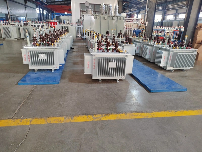
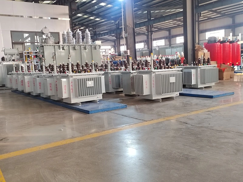
Conclusion: A transformer is not simply an iron core and coils, but a sophisticated system composed of subsystems such as the iron core, windings, oil tank, insulation, cooling, and protection. Each component carries a specific and irreplaceable function. When they work together, they achieve smooth power transmission and flexible voltage transformation.

In power transformer applications, selecting the right cooling method is critical for efficiency, lifespan, and operational safety. Among the most widely used transformer cooling systems are ONAN and ONAF cooling methods. Understanding the differences between these two systems helps utilities, industrial plants, and electrical engineers choose the best transformer solution for their projects.
As global power demand continues to grow in 2026, utilities, factories, renewable energy plants, and commercial facilities are increasingly choosing oil filled transformers for reliable and efficient power distribution. Compared with dry-type transformers, oil immersed transformers provide superior cooling performance, higher overload capacity, and longer service life in demanding environments.
Hot spot temperature is one of the most critical factors affecting the lifespan, efficiency, and operational safety of oil immersed transformers. Excessive hot spot temperatures accelerate insulation aging, reduce transformer reliability, and increase the risk of unexpected failures. For industries relying on continuous power supply, maintaining optimal transformer temperature is essential for long-term performance.Modern power systems widely use both ONAN transformer and ONAF transformer cooling methods to control internal heat generation and improve transformer stability. As a professional transformer manufacturer, Qingdao Haiyifeng Industry and Trade designs and manufactures high-efficiency oil immersed transformers engineered for superior thermal performance and lower hot spot temperatures.According to recent 2026 SEO and AI-search optimization trends, structured technical content with direct answers, practical solutions, and clear engineering explanations performs best for both Google Search and AI-driven search engines.
Choosing the right transformer is one of the most important decisions for industrial project developers and engineers. Factors such as energy efficiency, cooling performance, installation environment, operational lifespan, maintenance costs, and load capacity must all be considered carefully.
Among the most widely used transformer types in industrial applications are the oil immersed transformer and the dry type transformer. Each has its own advantages, disadvantages, and ideal application environments.
Power transformers play a vital role in alternating current (AC) power systems. Their main functions include voltage conversion, power transmission, and electrical isolation. By stepping up or stepping down voltage levels, they enable long-distance power transmission with minimal energy loss and ensure safe distribution to end users.
Did you know? Without transformers, the modern power system would be impossible. High-voltage electricity from power plants is stepped down through a series of transformers before being safely delivered to your home's electrical outlet. These silent "power guardians" work every day, but few people truly understand their internal components and their respective functions.
The three main functions of an electrical transformer are to increase or decrease voltage levels (voltage transformation), enable efficient long-distance power transmission, and provide electrical isolation between circuits.
Exploring the disruptive advantages of Haiyifeng transformer's 3D wound core oil-immersed transformers in power distribution. As a national-level manufacturing single-item champion enterprise, Haiyifeng transformer's with its unique amorphous alloy 3D wound core and other energy-saving core technologies, provides power systems with superior cooling efficiency, stronger insulation protection, and sustainable energy transmission solutions.
In our previous overview, we discussed the basic types and properties of transformer oil. However, engineers and maintenance teams often face real-world challenges: Which oil is best for a tropical substation? How often should dielectric strength be tested? Can I top up a mineral‑oil transformer with ester oil? This article provides quantitative benchmarks, a decision framework, and hands‑on maintenance procedures to help you extend transformer life and avoid costly failures.


Copyright © 2025 by Qingdao Haiyifeng Industry and Trade Co.,Ltd. All Rights Reserved
PRIVACY POLICY